1. INTRODUCTION
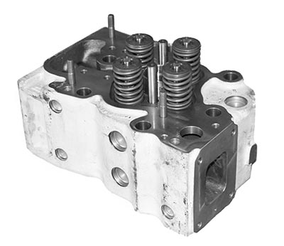
This Product Information sheet aims to describe clearly the process for reconditioning worn cylinder heads of gas and diesel engines (at the cylinder head supplier's works).
2. RECONDITIONING AND TEST INSTRUCTIONS
2.1. Strip cylinder head
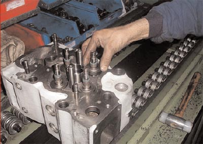
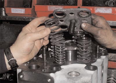
In a press, disassemble the half-cones using tool ref. 16.78.450. Remove the top plates, outer and inner valve springs, and bottom plates. Remove the valves from the cylinder head. In case of HGM560 engines, scrap all the parts you have disassembled. In case of other engine models, scrap all the components except for the springs and plates that can be reused after degreasing and washing, provided however that they show no bumps or damage whatsoever (if damaged, scrap them too).
When using reclaimed outer and inner valve springs, before fitting them into the cylinder head, check their length to see if they meet the drawing tolerance requirements, i.e. L=67.1+/-2.03 mm and L=56.6+/-1.73 mm respectively, to provide adequate spring load. Remove all the valve seats with tool ref. 16.75.570. Remove the valve guides with their retainer, by introducing the puller ref. 16.75.058 through the firing face of the cylinder head. Scrap the valve guides and seats. Also scrap the rotocaps from diesel cylinder heads.
2.2. Wash and hydraulic test
Degrease and wash the cylinder head with a hydrocleaning machine (water jet and soap). Dry with compressed air. In the event of gas cylinder heads fitted with either aluminium M8x1 screw plug or simply Loctite-glued, unclinched brass screw plugs, on new coolant passages on rocker arm side and on the side bevel near the exhaust face, follow the procedure described below:
- The three Loctite-glued unclenched and not deflashed brass screw plugs shall be removed, if possible, and relocated according to the assembly instruction of the re-drilling procedure that follows.
- As for the three aluminium screw plugs, re-drill according to the procedure that follows
Air test the internal circuits of the cylinder head at a pressure of 6 kg/cm2. If the sand draining plugs leak, change them and repeat the hydraulic test. Scrap all the cylinder heads that fail to pass this test. As regards gas cylinder heads with leaks through the M8x1 brass screw plugs on the rocker arm side and on the side bevel near the exhaust face for sealing the new coolant passages, the following re-drilling procedure shall apply in order to recover them:
- Re-drill the leaking hole with a 9mm diameter bit, if on the rocker arm side, using tool ref. 99.75.110 designed for this rework process for referencing purposes.
- Chamfer the hole mouth and manually tap the hole with an M10x1 hand tap. Degrease and blow the tapped hole.
- Set the 10mm long M10x1-6gbrass screw plug ref. 1910219, with Loctite 270, but do not screw it home; let it protrude 1.5mm to 2mm.
- Clinch the screw plug. For this purpose, beat the periphery and edges of the thread (never the centre, to avoid collapse of the thread) with a knockout punch or ball-peen hammer.
- Grind true or stone any excess portion of clinched plug to make it flush with the cylinder head surface. Allow Loctite glue to dry for at least one (1) hour.
NOTE: Where you have to change M10x1 screw plugs, use the same procedure, but mount M12x1 studs instead.
2.3. Clean and check firing face
Reface all the machined surfaces of the cylinder head with a fine scratch brush to remove any rust and paint residues. Inspect these areas visually for bumps, marks, etc.
Check flatness of the firing face with a precision ruler and a set of gauges. If surface deformation of the firing face is greater than 0.076mm and less than 0.150mm, grind the surface. Where deformation is greater than 0.150mm, scrap the cylinder head.
Bumps that cannot be eliminated totally by brushing within the specified tolerances shall give cause for scrapping the cylinder head.
Check the cylinder head height:
a) 140 +0.05 / 0, maximum wear limit of 139.85mm for Diesel and FGLD/SFGLD/SFGM/HGM240 engines.
b) 165 ±0,1, maximum wear limit of 164,85mm for HGM560 engines.
Scrap the cylinder head if thickness is smaller than the wear limit.
2.4. Clean the bottom of the valve seat housings
Clean the bottom of all valve seat housings (recesses) in the cylinder head with a reamer moving in the valve guide housings in the cylinder head.
2.5. Check valve guide and valve seat housings
Check the valve guide diameter (Ø 20 H6+0.013/0) with a go-no go gauge. Also check the diameter and depth of the valve seat housing (see table) with a go-no go gauge or inside diameter measuring caliper and a depth micrometer respectively.
|
CYLINDER HEAD TYPE |
VALVE SEAT HOUSING |
HOUSING DEPTH |
|
F/SF Diesel cylinder head |
Ø 55 H7+0,03 / 0 |
12,5 +0,1 / 0 |
|
FGLD/SFGLD/SFGM/HGM240 gas cylinder head |
Ø 55 H7+0,03 / 0 |
12,5 +0,1 / 0 |
|
HGM560 Gas cylinder head intake |
Ø 57,4 H7+0,03 / 0 |
14 +0,1 / 0 |
|
HGM560 Gas cylinder head Exhaust |
Ø 55,5 H7+0,03 / 0 |
14 +0,1 / 0 |
Check perpendicularity of the contact surface of the valve seat with the housing of the valve guide, perpendicularity measuring tool ref. 92.61.016, to be within maximum wear limit of 0.100 x 55mm. Check concentricity of guide and seat housings, eccentricity tool ref. 92.61.015, to be within maximum wear limit of 0.08mm.
Record the cylinder head number and the readings on document G-10-48. When specifications are not met, scrap the cylinder head.
2.6. Stamp reconditioning identifier
Stamp one letter "Z" for each rework on the cylinder head, in the rough casting side area near the intake ports.
2.7. Fit and check guides
Fit the four valve guides, use corresponding tools (see table).
|
CYLINDER HEAD TYPE |
Intake tool |
Intake Guide |
Exhaust tool |
Exhaust tool. |
|
F/SF Diesel cylinder head |
16.75.059 |
19.10.179 |
16.75.059 |
19.10.179 |
|
FGLD/ SFGLD/SFGM/HGM240 Gas cylinder head |
16.75.059 |
19.10.179 |
16.75.059 |
19.10.179 |
|
FGLD/ SFGLD/SFGM/HGM240 LF Gas cylinder head |
16.75.059 |
19.10.179 |
16.75.059 |
19.10.296 |
|
HGM560 Gas cylinder head |
19.75.051 |
19.10.241 |
19.75.052 |
19.10.287 |
Check the inside diameter of the valve guides as mounted (Ø 11.027 -11.037) preferably with a calibrated ring and pneumatic bore gauge or with a Go / No Go gauge Record the inside diameter values of the valve guides on document G-10-48.
2.8. Fit and check valve seats
With tool ref. 16.75.043, fit the valve seats, ensuring that seat is in contact with the housing bottom.
IMPORTANT!: Check for correct seating of the bottom of the seat onto the cylinder head by checking in 4 points
at 90° from each other by means of a 0.02mm gauge, which should not go.
|
CYLINDER HEAD TYPE |
Intake valve seat. |
Exhaust valve seat |
|
F/SF Diesel cylinder head |
16.10.564 |
16.10.565 |
|
FGLD/ SFGLD/SFGM/HGM240 Gas cylinder head |
19.10.026 |
19.10.026 |
|
HGM560 Gas cylinder head |
19.10.262 |
19.10.263 |
The load pressure in the press shall not exceed 2.5tons.
2.9. Mill valve seat chamfers
Mill the valve seat chamfers, using the following tools: Template ref. 16.75.061 and
|
CYLINDER HEAD TYPE |
Intake mill |
Charact. |
Exhayst Mill |
Charact. |
|
F/SF Diesel cylinder head |
16.75.105 |
120º (Amarillo) |
16.75.104 |
90º (Rojo) |
|
FGLD/ SFGLD/SFGM/HGM240 Gas cylinder head |
19.75.002 |
140º (Blanco) |
19.75.002 |
140º (Blanco) |
|
HGM560 Gas cylinder head |
19.75.056 |
140º |
19.75.057 |
120º |
Blow swarf off, protecting the cell with the purposely-installed screen.
Record the concentricity and perpendicularity data of the milled valve seat chamfer to the guide axis on document
G-10-48
2.10. Assemble the remaining cylinder head components
Oil and fit new intake and exhaust valves.
|
CYLINDER HEAD TYPE |
Intake valve |
Exhaust valve |
|
F/SF Diesel cylinder head |
19.10.555 |
19.10.551 |
|
FGLD/ SFGLD/SFGM/HGM240 Gas cylinder head |
19.10.183 |
19.10.183 |
|
HGM560 Gas cylinder head |
19.10.243 |
19.10.244 |
With a dial gauge, check for valve recession on firing face: Gas cylinder head (1.2 +0.30/-0.05); Diesel cylinder head, intake (1.1 +0.5) and exhaust (1.1 +0.45). On one in every ten (10) cylinder heads, check for minimum contact between valve and seat to be 80%, using ‘Prussian blue’. Check valve vacuum with an air removal system and sucking pump.
Record valve recession and valve vacuum leak data on document G-10-48.
Fit the others components of the cylinder heads (see table), press-fit the entire assembly with tool ref. 16.75.099 and fit the half-cones ref. 16.10.079.
|
CYLINDER HEAD TYPE |
Valve Retainer |
Bottom valve plates |
Top valve plates |
Inner spring |
Outer spring |
|
F/SF Diesel cylinder head |
16.10.072 |
16.10.075 |
19.10.081 |
16.10.337 |
16.10.336 |
|
F/SF Diesel out of specif. cylinder head |
16.10.566 |
16.10.075 |
19.10.545 |
16.10.337 |
16.10.336 |
|
FGLD/FGLD/SFGM/HGM240 Gas cylinder head |
16.10.072 |
16.10.235 |
19.10.081 |
16.10.337 |
16.10.336 |
|
HGM560 Gas cylinder head |
16.10.072 |
19.10.245 |
19.10.081 |
19.10.247 |
19.10.246 |
On document G-10-48, record distance from top plate to face of in-head rocker arm, for further reference in case of any change of same during field checks. (Theoretical measurement is 51.9 to 52.4mm for gas cylinder head FGLD/SFGLD/SFGM/HGM240; 51.873 to 52.373mm at exhaust of diesel cylinder head and 42,5 to 43 mm for HGM560 cylinder heads).
3. DIRECTIONS FOR USE
Instruction IM-01-99 “Rework of cylinder heads for F and SF diesel and gas engines” and document G-10-48 “Reconditioned Cylinder Head Data Sheet” duly filled in shall be sent to GUASCOR Quality Department. A copy of document G-10-48 shall accompany the container of cylinder heads at all times, to serve as a follow-up sheet once the reconditioning process has finished.
4. RELATED DOCUMENTS
- IM-01-99: “Rework of cylinder heads for F and SF diesel and gas engines”.
- G-10-48: “Reconditioned Cylinder Head Data Sheet” (see Annex).
5. ANNEX: RECONDITIONED CYLINDER HEAD DATA SHEET
 1910930 / 1910B70 reconditioning using 1977330 cylinder head reconditioning kit |
 1910930 / 1910B70 reconditioning using 1610336 & 1610337 valve springs |
Below is part of document G-10-48 “Reconditioned Cylinder Head Data Sheet” to be used by the cylinder head repair shop for recording the specified data. Гуаскор, клапаны двигателя
|
Reference: |
|
Quantity: |
|
Supplier |
||||||||
|
Part name: |
|
Date Launched: |
|
|
||||||||
|
Cylinder head nr. |
|
|
|
|||||||||
|
|
AA |
AE |
EA |
EE |
AA |
AE |
EA |
EE |
|
|||
|
Concentric.(max 0.08)/Perpendicul.(max 0.100) of valve seat Ø55 to valve guide Ø20 |
|
|
|
|
|
|
|
|
|
|||
|
Valve guide inside Ø (Go/No Go) |
|
|
|
|
|
|
|
|
|
|||
|
Valve-to-firing face height: Gas (1.2 +0.30/-0.05) Diesel I (1.1 +0.5) E (1.1 +0.45) |
|
|
|
|
|
|
|
|
|
|||
|
Valve vacuum leak test result |
|
|
|
|
|
|
|
|
|
|||
|
Concentric.(max 0.05)/Perpendicul.(max 0.05) of valve seat chamfer to guide |
|
|
|
|
|
|
|
|
|
|||
|
Distance from top plate to face of rocker arms |
|
|
|
|
|
|
|
|
|
|||
|
Refacing of firing face YES / NO |
|
|
|
|||||||||
|
Number of reworks |
|
|
|
|||||||||
|
Cylinder head nr. |
|
|
|
|||||||||
|
|
AA |
AE |
EA |
EE |
AA |
AE |
EA |
EE |
|
|||
|
Concentric.(max 0.08)/Perpendicul.(max 0.100) of valve seat Ø55 to valve guide Ø20 |
|
|
|
|
|
|
|
|
|
|||
|
Valve guide inside Ø (Go/No Go) |
|
|
|
|
|
|
|
|
|
|||
|
Valve-to-firing face height: Gas (1.2 +0.30/-0.05) Diesel I (1.1 +0.5) E (1.1 +0.45) |
|
|
|
|
|
|
|
|
|
|||
|
Valve vacuum leak test result |
|
|
|
|
|
|
|
|
|
|||
|
Concentric.(max 0.05)/Perpendicul.(max 0.05) of valve seat chamfer to guide |
|
|
|
|
|
|
|
|
|
|||
|
Distance from top plate to face of rocker arms |
|
|
|
|
|
|
|
|
|
|||
|
Refacing of firing face YES / NO |
|
|
|
|||||||||
|
Number of reworks |
|
|
|
|||||||||
Verified 2017 September - silindir kapak


